


[06]
2025
Project
[Design]
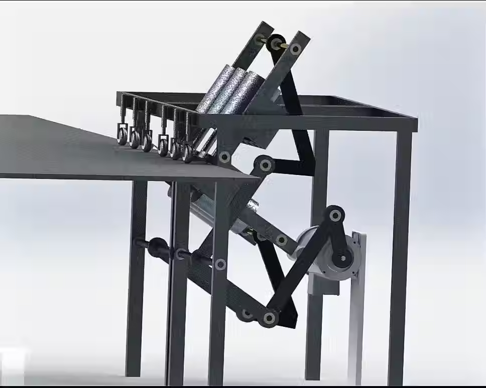
Assembled Machine View
Illustrative concept to demonstrate methods; parameters are intentionally generic. Any resemblance to real designs is coincidental. Content policy: T&Cs.
[06]
2025
Project
[Design]

Exploded Side View
Illustrative concept to demonstrate methods; parameters are intentionally generic. Any resemblance to real designs is coincidental. Content policy: T&Cs.
[06]
2025
Project
[Design]

Exploded Side View
Illustrative concept to demonstrate methods; parameters are intentionally generic. Any resemblance to real designs is coincidental. Content policy: T&Cs.
Industrial Mulitiaxial Polisher Machine
[06]
2025
Project
[Design]


Range of Visal Facets and Variations of Project.
Illustrative concept to demonstrate methods; parameters are intentionally generic. Any resemblance to real designs is coincidental. Content policy: T&Cs.

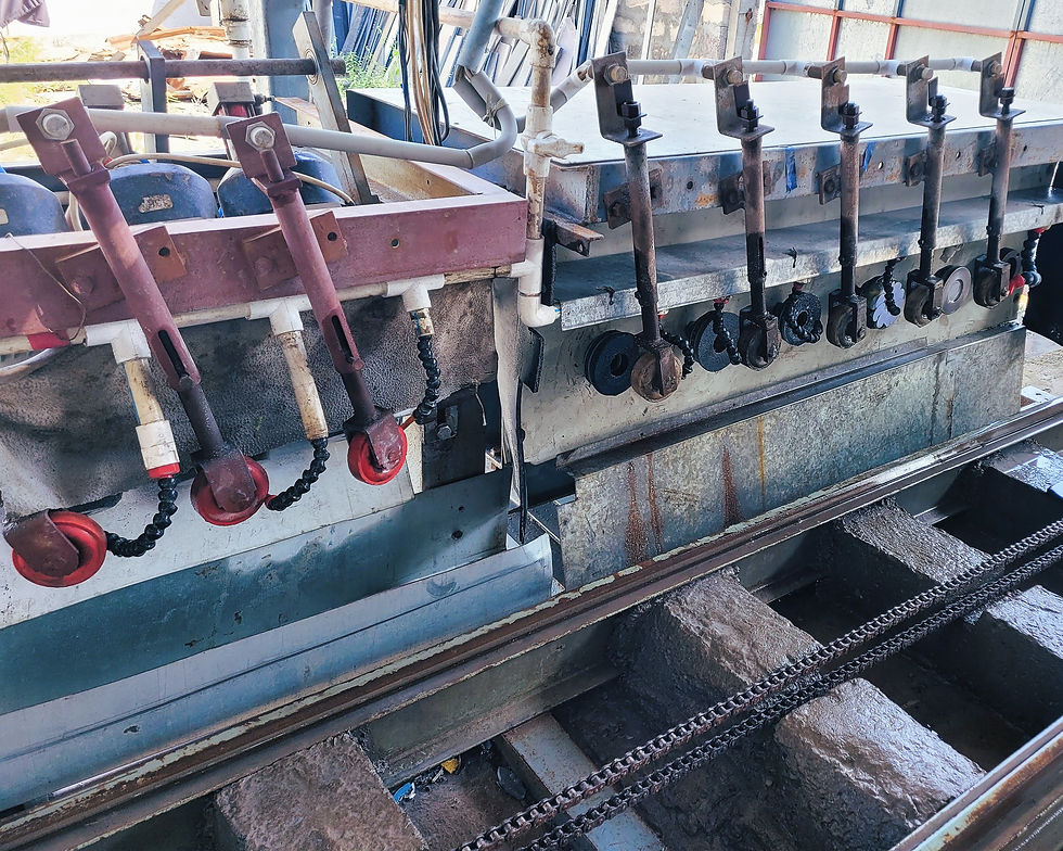
Industrial Multiaxial Stone-Edge Polisher
Design and manufacture a granite‑edge polishing machine capable of multi‑directional manoeuvres that deliver mirror‑quality finishes at production speed while remaining cost‑competitive.
Working Details
Phase 1: Requirements & Manoeuvre Catalogue – Established budget ceilings and durability targets, then mapped a sequence of polishing manoeuvres optimised for throughput, edge quality, and long‑term reliability.
Phase 2: Primary Edge Correction – Addressed the non‑vertical edges left by slab cutting with five sequential polishers of graduated grit, aligned perpendicular to the slab face to achieve an initial mirror finish.
Phase 3: Final Shine & Safety – Integrated six additional polishers arranged as two tri‑motor pairs acting 90° apart along the edge. Each half‑ton waterproof motor applied ~70 N m² perpendicular load while executing a radial path via a four‑bar linkage sized using an RDF cycloidal‑didial polynomial for the required oscillatory effect.
Phase 4: Kinematic Design – Derived linkage lengths and cam profiles to maintain synchronous motion and uniform contact pressure across variable slab geometries, using SolidWorks motion studies and Fusion 360 validation loops.
Phase 5: Fabrication & Assembly – Machined structural and kinematic components on VMCs, applied GD&T for interchangeability, and integrated pneumatic jacks and proximity sensors for automated in‑feed control. Field assembly by technicians resulted in a fully operational system at roughly one‑tenth the cost of a comparable Chinese import.
Post‑commission tests confirmed edge accuracy, surface roughness, and cycle time met or exceeded benchmarks, validating the controlled‑loop architecture and synchronous drive strategy.
Tools and Skillset
SolidWorks & Fusion 360 CAD/CAM
RDF cycloidal‑didial cam synthesis
Four‑bar linkage kinematics
Pneumatic jack & sensor integration
PLC programming (Kinko drive)
GD&T
VMC machining
Synchronous multi‑motor control
Design‑for‑Cost optimisation


